Flared steel wire + insert moulding + finished assembly
A load-bearing handle built around a flared steel wire.
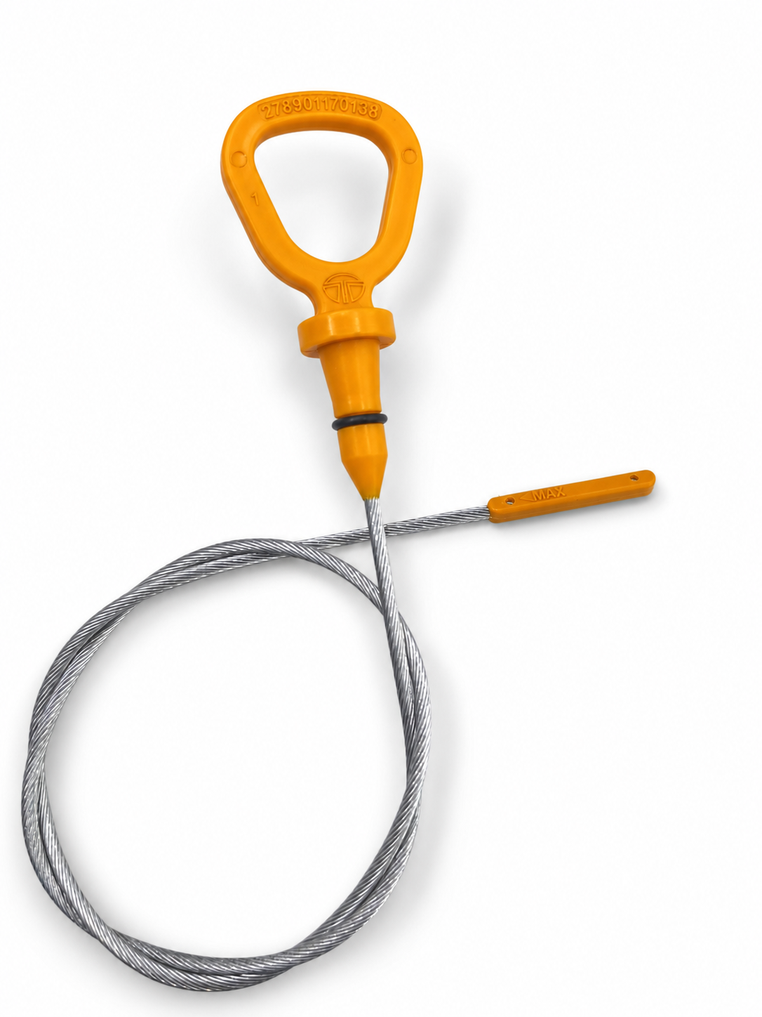
The customer needed a finished wire-handle assembly ready for an 8 kg load test. We flare the multi-strand steel wire, insert-mould the polymer handle, and fit the sealing O-ring before supplying the completed assembly.
01 | Prepare the wire insert
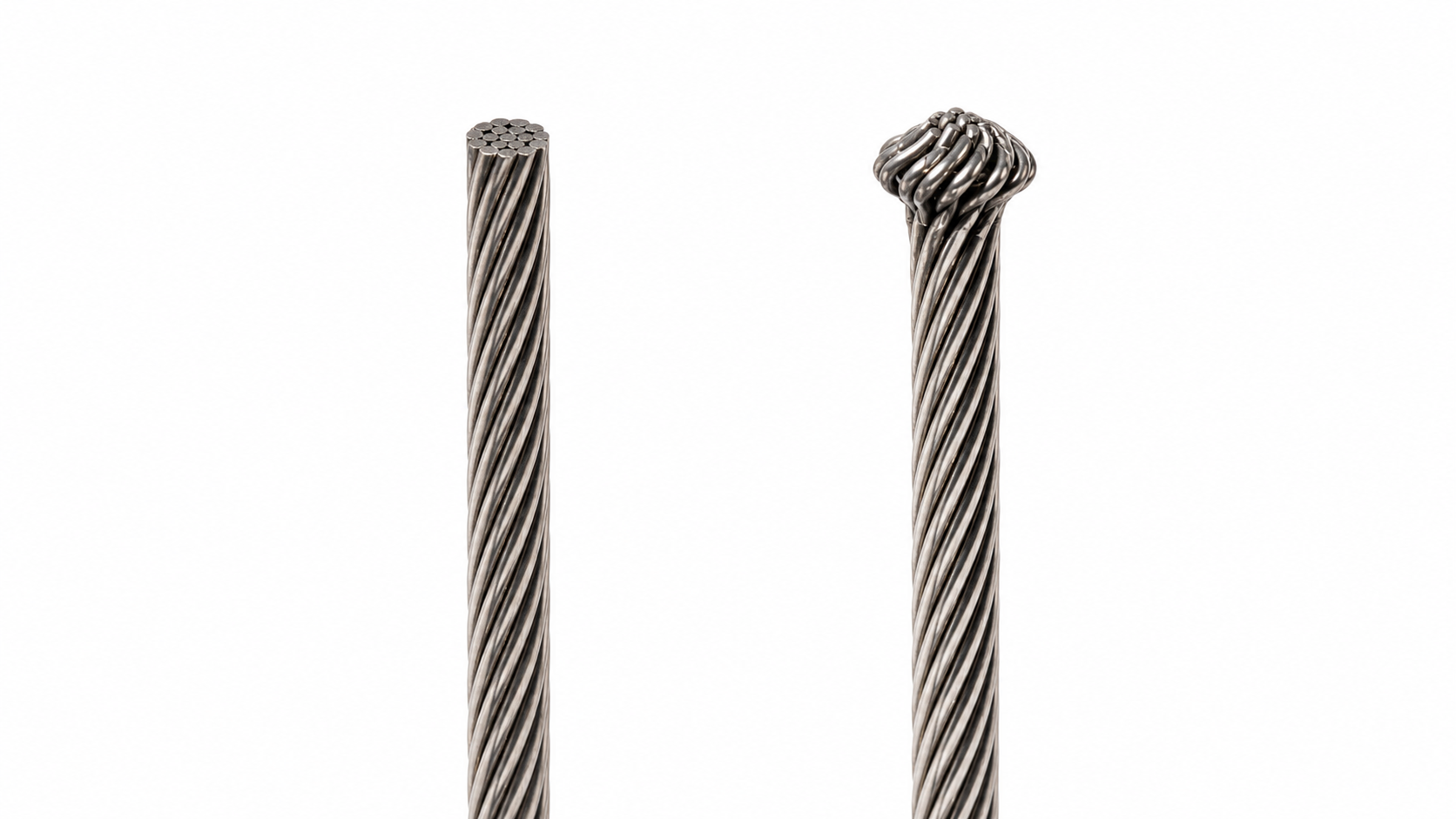
The flare strengthens the wire-to-handle joint.
The insert is a 3 mm or 4 mm multi-strand steel wire. Before moulding, we spread the strands at the embedded end to create the flare shown here. The larger end locks into the surrounding polymer and helps the assembly carry the required load.
02 | Position and insert-mould
The prepared wire must sit correctly in the tool.
We place the flared end at the required depth and position, then mould the polymer handle around it. This joins the prepared wire and the moulded body in one repeatable assembly.
03 | Fit the customer-specified O-ring
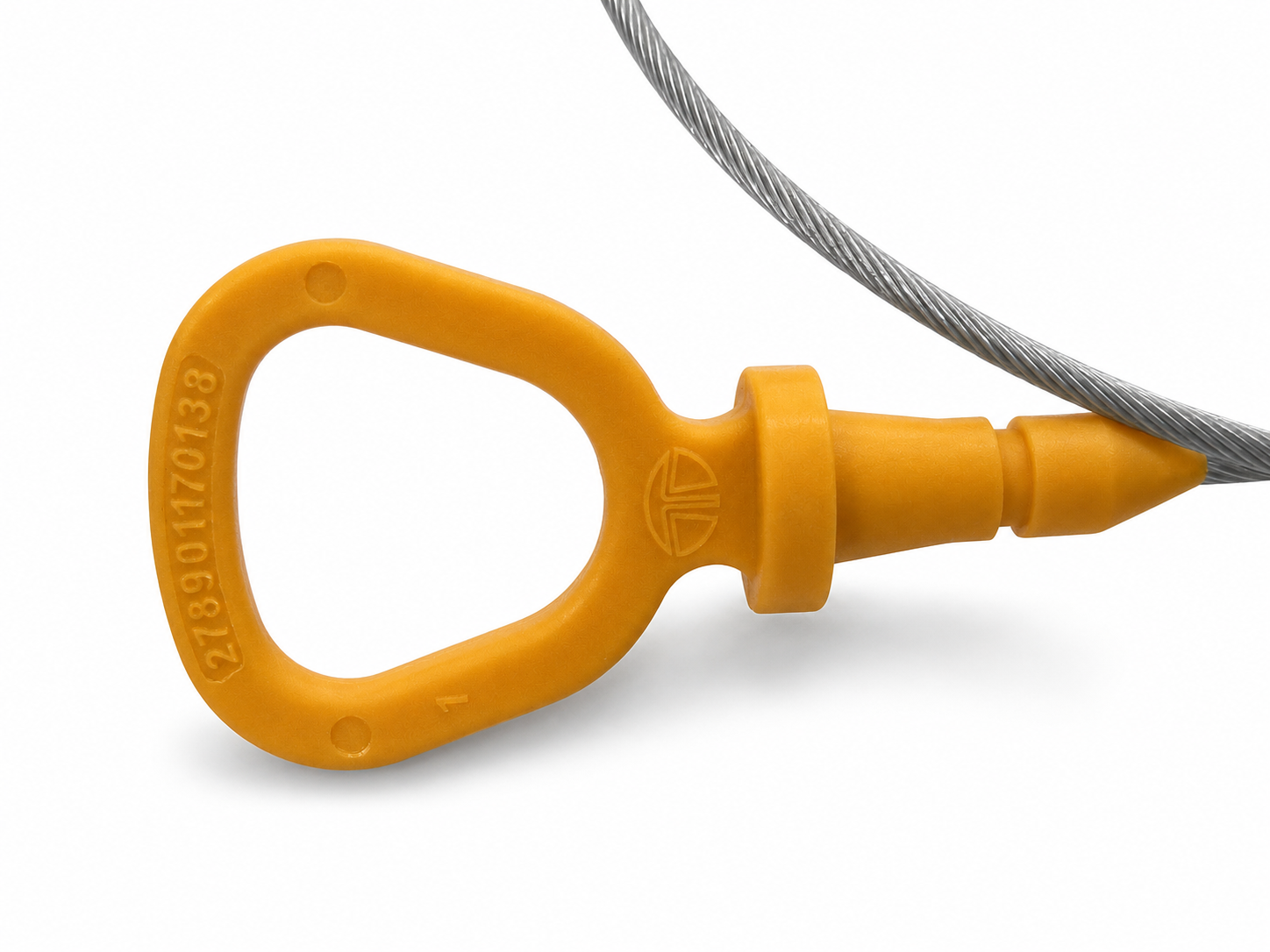
The customer receives a finished part, ready to test.
After moulding, we fit the customer-specified O-ring and supply the handle, wire and O-ring as one finished assembly. Customer feedback on the supplied assemblies has not identified a defect in the specified 8 kg load test.
Load-bearing joint
The flare forms the mechanical lock.
The embedded wire end is deliberately widened before moulding. Once the polymer forms around it, that shape resists pull-out and carries the load through the handle.
Scope of supply
Parshwa Plastics supplies the completed assembly.
We handle the wire preparation, flaring, insert placement, moulding and O-ring fitment. The customer receives one complete assembly, ready for testing, from one supplier.
Later production changes
We adapted the tool as the part family grew.
The original requirement did not include every part number, date mark or the customer logo. Those details were added as the programme developed. We made interchangeable steel inserts so each run can be set for the required drawing: one of 87 part numbers, three moulded-part colours, three O-ring colours, and either 3 mm or 4 mm wire. The production month and year are set in the tool at the same time.
04 | Change the part number
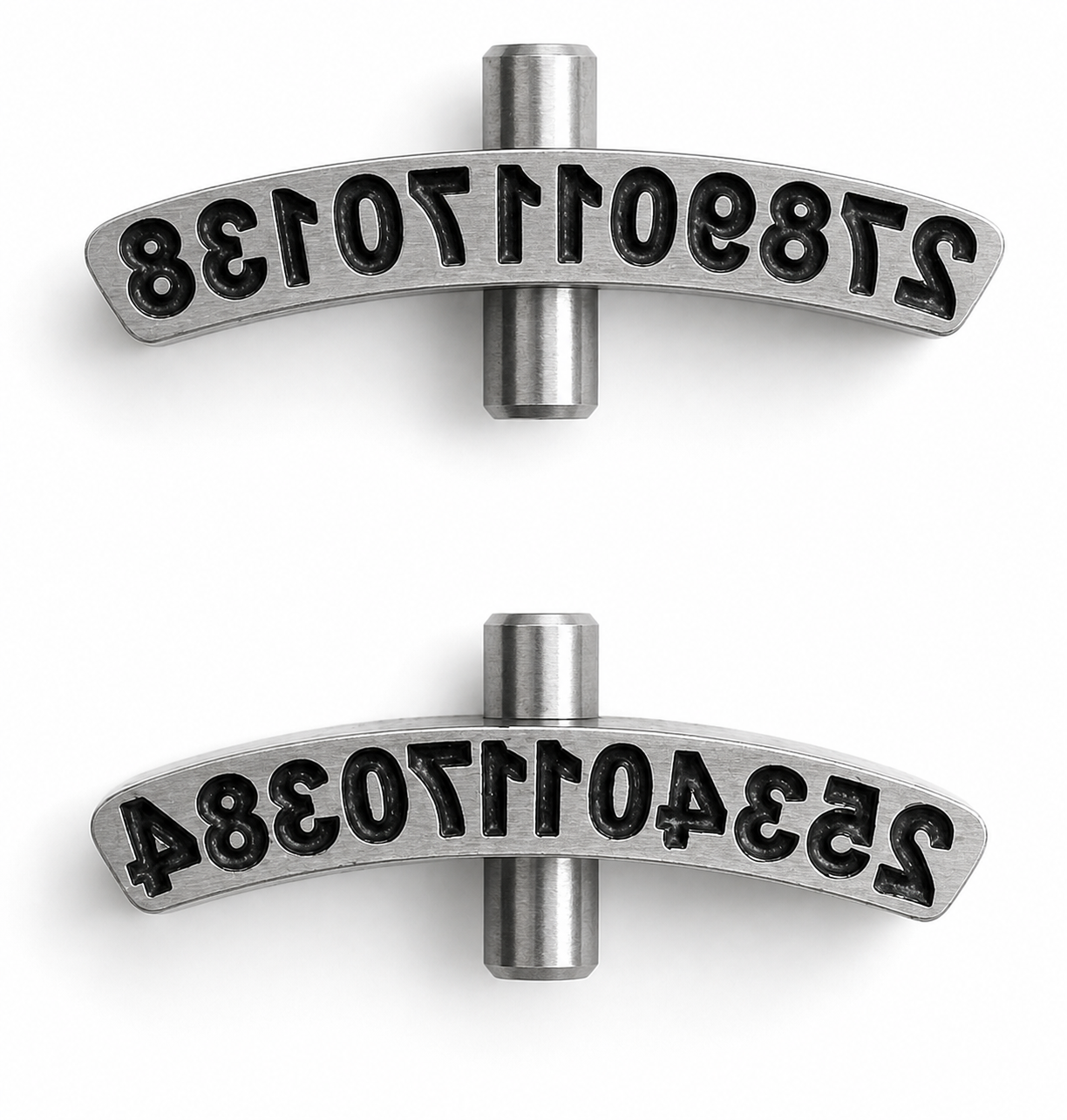
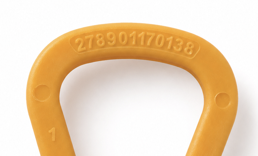
Each mould supports all 87 numbered parts.
Each part number sits on its own mirrored steel insert. We operate four identical moulds so production can run across four machines, and every mould accepts the same interchangeable number inserts. The operator fits the correct insert before moulding, allowing any of the 87 numbered parts to run in any mould without requiring a separate mould for each number.
05 | Set the production date
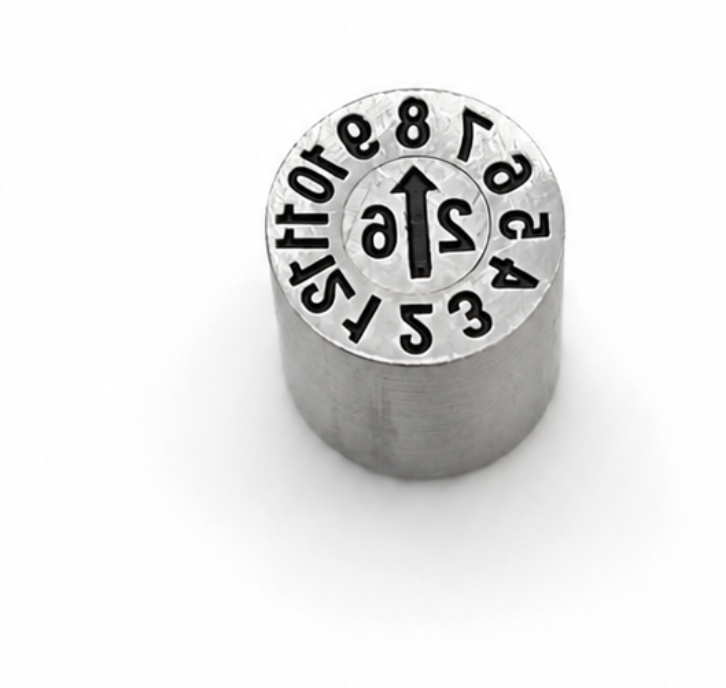
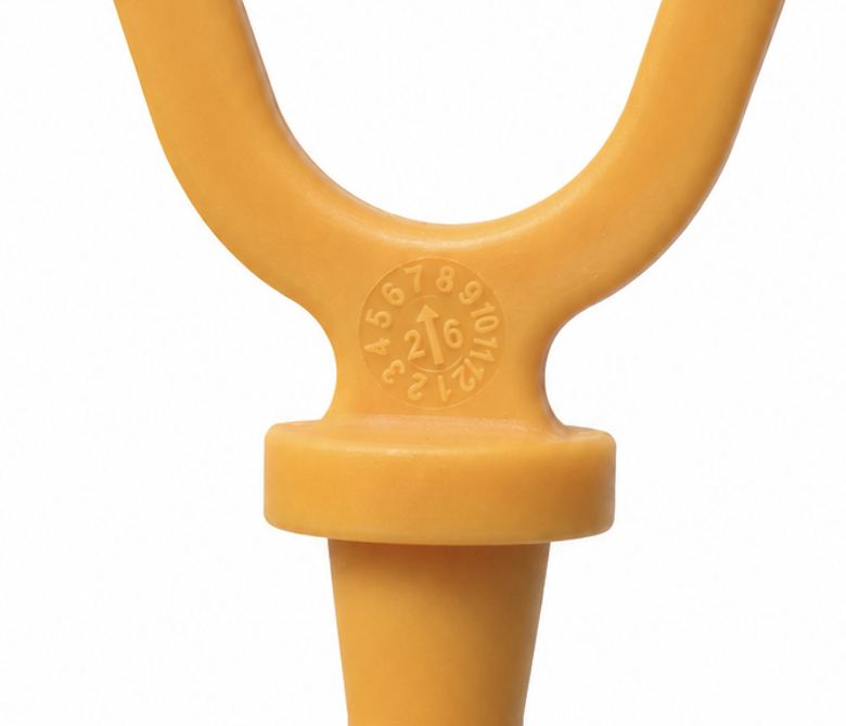
The month and year are moulded into every part.
The centre of the date insert carries the year. Before the run, a screwdriver turns the arrow to the production month. The date then leaves the mould as part of the handle.
06 | Add the customer logo
The same part now carries two OEM logos.
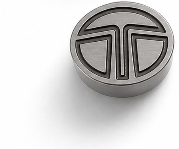
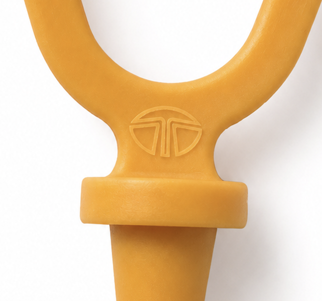
We were already moulding this part with one OEM logo when the same component was required for a second OEM. We made an interchangeable steel punch for the second logo and fitted it into the existing tool. The operator can select the required punch before each run, so one mould produces either branded version.