
Prepared metal insert + glass-filled nylon + center-referenced machining
Metalwork. Insert molding. Final machining.
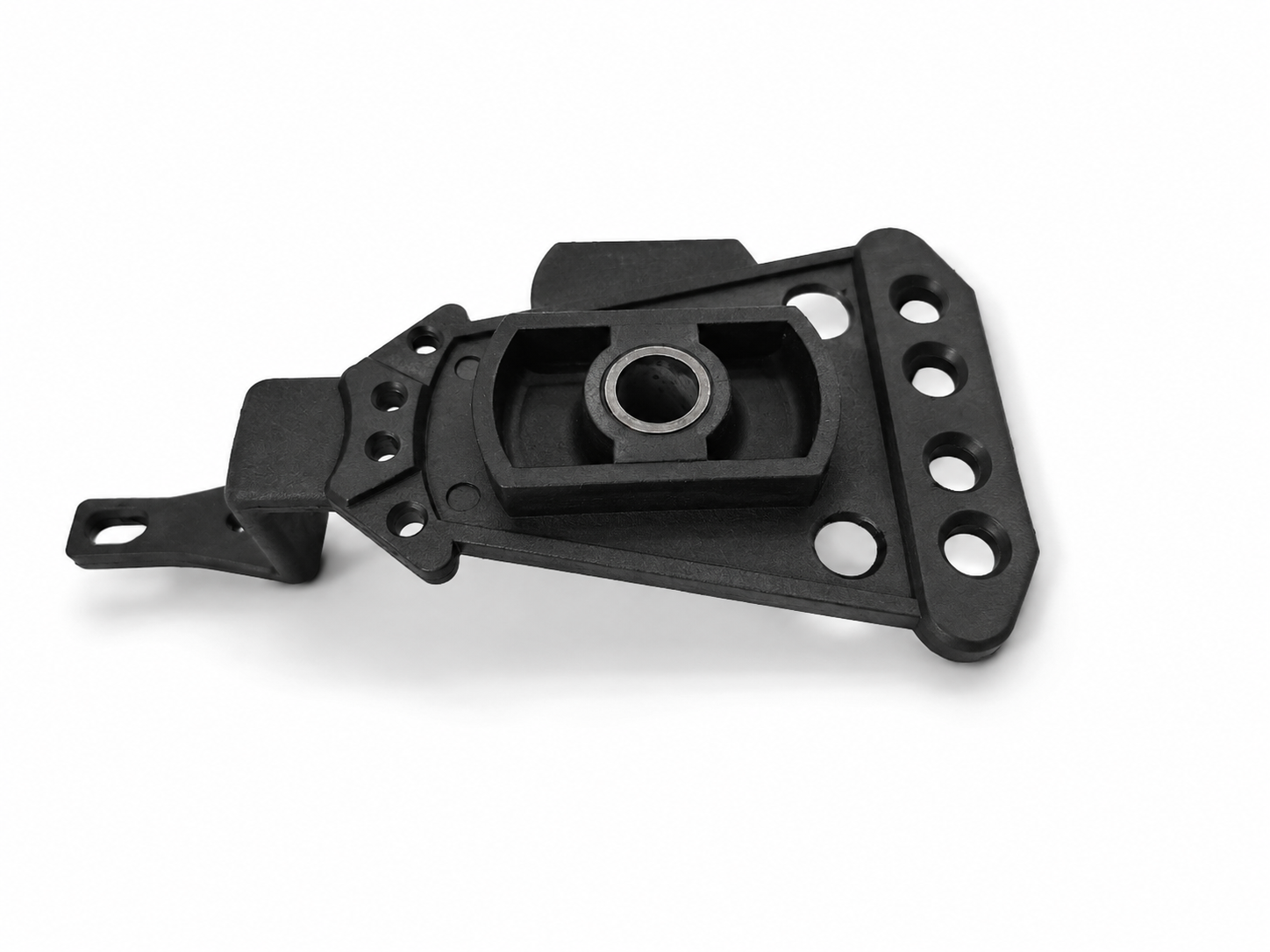
This bell crank lever combines a prepared metal insert, glass-filled nylon insert molding, and center-referenced final machining. We manage the sequence so the finished part holds its alignment in continuous high-speed use.
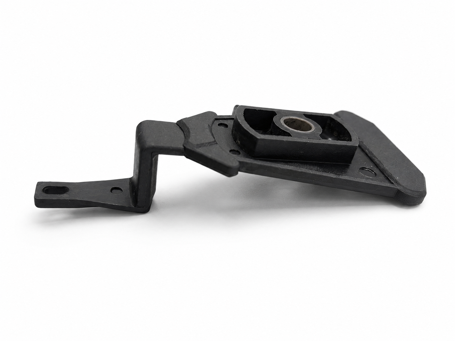
01 | Prepare the Metal Core
Ream, grind, and nitride before molding.
The metal insert is prepared before the polymer stage begins. Reaming establishes the center bore, grinding controls the working surfaces, and nitriding hardens the core for continuous service.
02 | Insert Molding
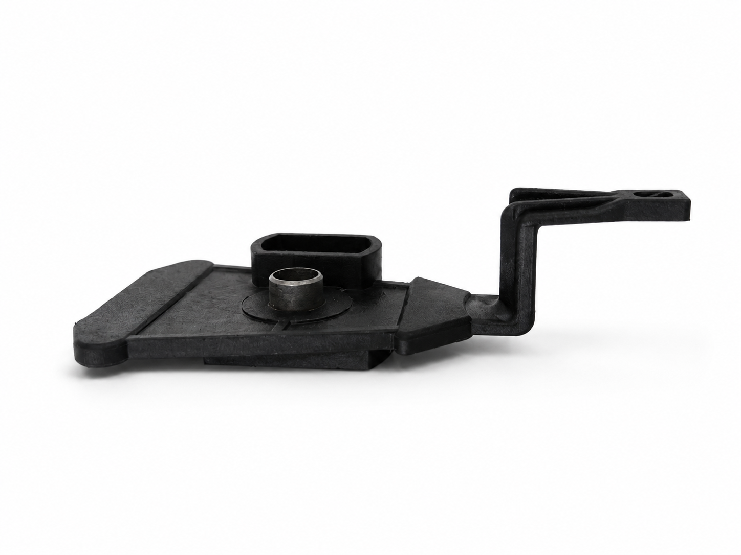
Glass-filled nylon is molded in-house.
We insert-mold the prepared core using Nylon-6 with 30% glass fiber and MoS2. The material combination gives the lever the strength and low-friction performance needed for continuous movement.
03 | Machine from One Reference
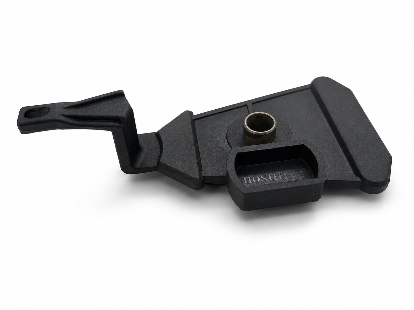
The center hole controls the final alignment.
After molding, the center hole becomes the reference for machining four exterior pads to 0.05 mm parallel alignment. Once the customer fits the ceramic guide, the finished lever runs in a textile texturizing machine at 1,200 RPM.
The Risk: Split Responsibility
Several processes still have to produce one aligned part.
Metal grinding, nitriding, insert molding, and secondary machining all affect the final geometry. When those steps are split across suppliers, alignment risk and follow-up increase.
The Solution: One Managed Sequence
One supplier controls the job from core to finish.
We coordinate the metalwork, insert-mold the body in-house, and manage the final machining. The finished part ships with the required inspection records and shipment documents.
Later Production Variation
Reduce oil churning without changing the mold.
After the original tooling was complete, the customer requested an oil-flow change. We added through-holes by secondary machining while keeping the existing mold in service.
04 | Post-Tooling Oil-Flow Openings
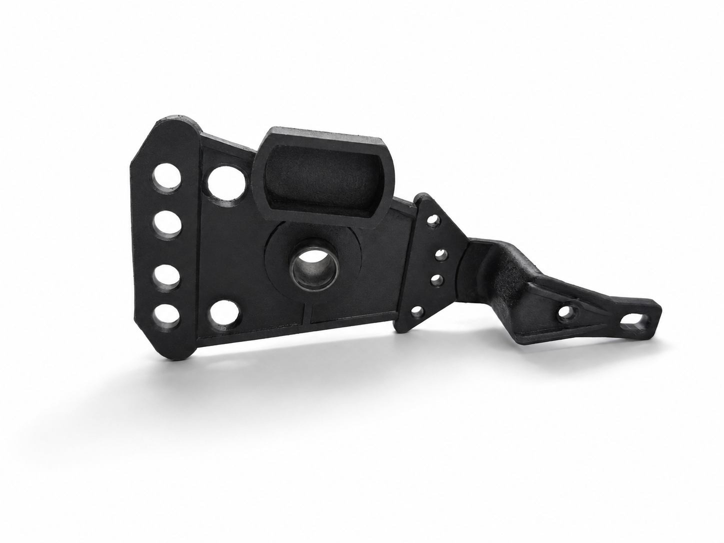
Through-holes reduce oil churning.
The lever rotates at 1,200 RPM inside an oil-filled housing. The machined openings give the oil a path through the lever, reducing pressure resistance and helping it circulate around the moving part.
The Constraint: Tooling Already Complete
The production mold was already made.
The oil-flow change was introduced after molding. Secondary machining added the openings while the original production tool stayed in service.
Our Contribution: Secondary Machining
We added the new feature after molding.
Parshwa Plastics incorporated the customer’s new through-hole pattern into the machining stage of the existing production sequence.